
Opera Neon is our first AI agentic browser designed for the next generation of the web.


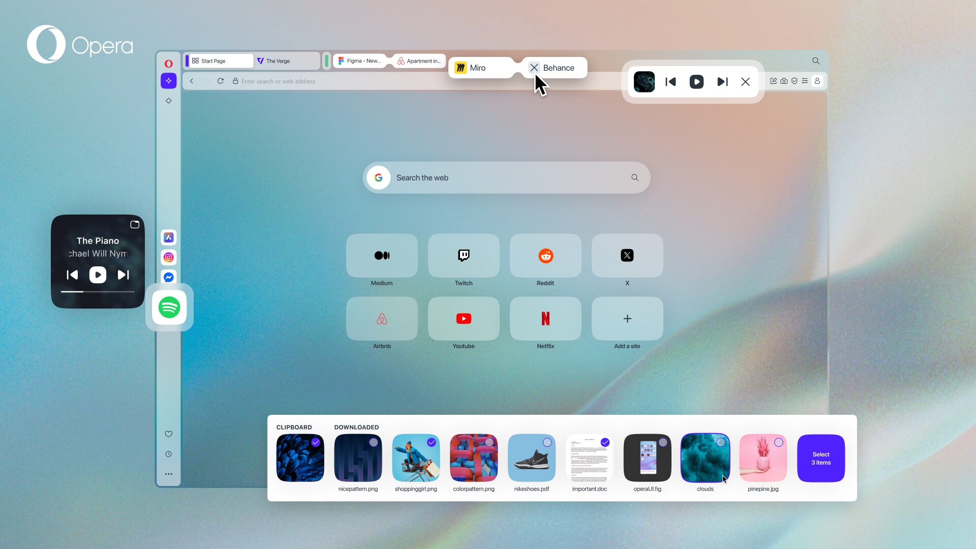


Opera's free VPN, Ad blocker, and Flow file sharing. Just a few of the must-have features built into Opera for faster, smoother and distraction-free browsing designed to improve your online experience.